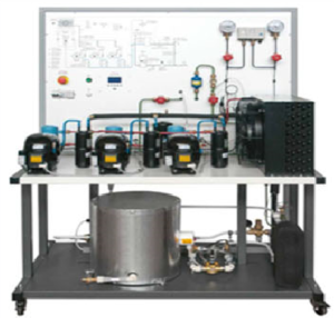
The trainer, properly designed for educational purposes, allows to study the combined operation of compressors in a refrigeration system controlled via a regulator or via a control unit/PC that switch on and off each compressor depending on the required cooling power. It includes a closed water circuit and a heater to apply a thermal load to the evaporator of the system.
TRAINING PROGRAM
• Study of the combined operation of compressors
• Study of the operation of a compressor pack controller
• Use of the p – h diagram of a refrigerant gas
• Collection of the operating data and calculation of the heat balances and system efficiency
• Electric power consumption measurement depending on the number of active compressors
• Effect of the airflow rate on the condenser performance
• Data acquisition, system supervision and fault insertion via PC
TECHNICAL SPECIFICATIONS
• Steel structure mounted on wheels, painted and treated in the oven
• Color silk-screen-printed schematic diagram of the hydraulic circuit with warning LEDs
• 3 hermetic compressors (2,0 kW refrigeration capacity, temperature: -10 + 35 °C)
• Variable flow air cooled condenser
• Oil separators, liquid separators, liquid receiver
• Check valves
• Sight glasses, drying filter
• Thermostatic expansion valve
• Water evaporator
• Valve for plant vacuum, refrigerant charging and recovering
• Pipes connecting the various components painted with different colors
• High and low pressure gauges
• Double pressure switch
• Water closed circuit, including 3-speed pump, storage tank, 1.500 W heater, thermostat, pressure gauge
• Compressor pack controller with high pressure sensor for condenser fan speed regulation and low pressure sensor for compressors management
• Complete set of instruments including:
– 4 digital thermometers with Pt100 probes to be inserted in many temperature test points along the hydraulic circuits
– Water flowmeter
– Digital multimeter
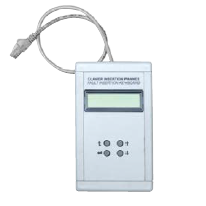
• Control unit with the following characteristics:
– Autonomous operation or Remote Control (via PC, not included in the equipment)
– USB interface for connection with PC
– Graphic LCD display for visualizing values and trend in time of input signals such as temperature, pressure, water flow
– Electronic board and converters for input signals
– Numerical keyboard
– Application software developed
– Fault insertion included
• Complete set of sensors including:
– 6 Pt100 temperature probes
– 1 water flow sensor
– 2 pressure sensors
– 1 electric power converter
• Thermomagnetic – earth leakage control button
• Emergency button
• Refrigerant: CFC free
• Power supply: 230 Vca 50 Hz single-phase – 3600 VA (Other voltage and frequency on request)
SPECIAL VERSION ON DEMAND:
Besides offering the characteristics of standard version, this version also includes:
• Fault simulator using switches, or
• Fault simulator operating with control unit