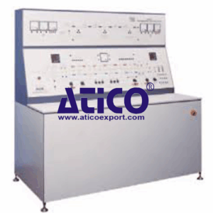
Description
Part of the Modular Power Systems range, the Switched Busbar Module simulates industrial power line switching and monitoring. Important note: This unit has no test circuit supplies or loads. To use it correctly, it must be connected to two or more units in the Modular Power System Laboratory range. The fully instrumented unit includes two main control panels: the upper panel and the lower panel. Each panel has a detailed mimic diagram. The lower panel has a double bus: a main bus and a standby bus or ‘reserve bus’. Each bus has two sections, split by circuit-breakers. Each bus includes individual bus section switches. Two bus-coupler switches connect the left and right-hand sections of the main bus and the standby bus. The lower front panel also includes six feeders (three on each side of the bus). They are bi-directional, so the user can set them as incoming or outgoing (sink or source) feeders. The feeders connect to the other modules of the Power Systems range (supplies and loads). Each feeder also has its own circuit-breaker and meters to measure and display the current and voltage at each feeder. One feeder includes a ‘point-on-wave’ circuit-breaker. This allows the user to study the transients created when an alternating current is interrupted (switched). The main bus, the standby bus and all feeders include current transformers (CTs). The user connects these to the protection relays to create ‘zone protection’ circuits and investigate faults applied to different parts of the double busbar system and the radial system. This is high impedance differential protection. The upper panel has a radial system of one incoming and three outgoing feeders. Each feeder includes a circuit-breaker, voltage and current meters, and current transformers for connection to the protection relay. The upper panel also includes test points for the double busbar and radial systems. These allow the user to connect faults or external loads (not supplied). The panel includes test/ fault switches, one with a digital timer. These allow the user to create open-circuit and short-circuit (line/line or line/earth) current faults and monitor their effects. The user connects and sets the protection relays to detect line and earth currents, voltage and frequency faults. The relays also monitor and measure fault events and disturbances for fault analysis. The user sets the relays from their local control panel, or by a cable link to a suitable computer (computer not included) and software (included). When the user applies a circuit fault, the relays open circuit-breakers in the test circuits. The circuit breakers also include hand-operated switches, and lamps. The lamps show whether the circuit-breakers are open or closed. For more experiments in protection, the unit has an extra socket to connect an additional protection relay (not supplied). Supplied with the equipment is a set of shrouded leads for the user to connect the test circuits together. The unit includes an emergency switch, a mains supply isolator and protection fuses. The Modular Power System Laboratory allows experiments on power generation, transformation, transmission, distribution, utilisation and protection. Supplied with a comprehensive user guide which includes equipment descriptions, theory and experiments. Also, the open and flexible structure of the equipment makes it ideal for student projects and for lecturers to create their own experiments
Features
- Connects other parts of Electrical Power Systems range to create realistic and meaningful electrical power systems, with characteristics typical of industrial plant
- Allows creation of fully functional electrical power systems so students can observe the interaction between elements ouble busbar with six bi-directional feeders
- Separate radial circuit with one incoming and three outgoing feeders
- Built-in industrial-standard digital protection relays give wide range of functions
- Includes ‘point-on-wave’ circuit breaker for switching transient investigations
- Fitted with socket for additional protection relay for more experiments
- Introduces ‘unit protection’
- Includes circuit protection, instruments and controls
- Two separate three-phase fault switches (one with a digital timer) allow students to apply a range of faults and monitor their effects on the whole system
Specifications
Nett dimensions and weight:
1850 mm x 1870 mm x 960 mm and 520 kg
Packed volume and weight:
5 m3 and 650 kg
Double bus circuit:
Six bi-directional feeders, each with circuit breakers, voltage and current meters and protection CTs for connection to the protection relays
Two circuit-breakers to break each half of each bus
Twelve bus isolators, six on each half of the bus
Two circuit-breakers that break the coupling between the main and reserve bus
Radial circuit:
One incoming and three outgoing feeders, each with circuit breakers, voltage and current meters and protection CTs for connection to the protection relays.
Protection relays:
Two identical industrial-standard digital relays for connection to the CTs around the circuits, for standard protection and zone protection.
Operating Conditions
- Operating Environment:
Laboratory - Storage Temprature Range :
–25°C to +55°C (when packed for transport) - Operating Temprature range:
+5°C to +40°C - Operating relative humidity range:
80% at temperatures < 31°C decreasing linearly to 50% at 40°C