Description :
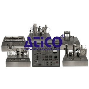
The Modular System for the Study of Sensors includes a wide range of units that
include different electronic components designed to control the signal produced by the transducers (Sensors and Actuators) on the one hand, and to evaluate and quantify it on the other hand. Therefore, the following units have been developed to show the fundamental principles of the different sensors and actuators and to understand in a practical way how to process the signals which they produce.
This unit is common for the different test modules type and can work with one or several modules. All elements are included in a metallic box.
Configuration : As listed below :-
Signal Conditioning Circuits :-
Amplifiers :-
DC Amplifiers : • Input Range : +/-12 VDC.
• Input Impedance : 100 KΩ.
• Adjustable Gain : 1, 10,100 for the Amplifier 1 and Amplifier 2
• Fixed Gain : 100 for X100 Amp.
AC Amplifier : • Input Range : 12 VAC.
• Adjustable Gain : 10, 100, 1000
• Bandwidth : 10-16000 Hz
Power Amplifier : • Input Range : 12 V max.
• Output Current : 1.5 A max.
• Output Power : 9 W max.
Current Amplifier : • Gain : 10,000.
• Output Current : 1 A max.
Buffers : • 2 Buffers.
• Input Voltage : 12 V max.
• Input Impedance : 100 KΩ.
Inverting Amplifier : • Input Voltage : 12 V max.
• Input Impedance : 100 KΩ.
• Gain : -1
Differential Amplifier : • Input Voltage : 12 V max
• Inputs Impedance : 100 KΩ (Input A) and 200 KΩ (Input B)
• Ad (Differential Gain) : 1.0
• Ac (Common Mode Gain) : 0.02 max
Instrumentation Amplifier : • Input Voltage : 12V max.
• Inputs Impedance : 100 KΩ.
• Ad (Differential Gain) : 1.0.
• Ac (Common Mode Gain) : 0.006 max.
Summing Amplifier : • Input Voltage : 12 V max.
• Inputs : 3 Nos.
• Gain : 1
Comparators : • Schmitt Trigger.
Filters : • 40 kHz Filter
• Pass-Band Filter : at 40 kHz.
• Low-Pass Filter : Selectable cut-off frequencies at 15 Hz, 1.44 Hz, 0.14 Hz.
Integrator : Selectable Time Constants : 100 ms, 1 s, 10 s.
Differentiator : Selectable Time Constants : 10 ms,100 ms, 1 s.
Sample / Hold Circuit : Time Constant : 1 ms.
Converters Circuits :-
Voltage to Current (V/I) Converter : • Output Current : ± 20 mA max.
• Transfer Ratio : 10 mA/V
Current to Voltage (I/V) Converter : • Output Voltage : ±2 V (6 V max.).
• Transfer Ratio : 0.1 V/mA.
Frequency to Voltage (F/V) Converter : • Transfer Ratio : 1 V/kHz.
• Max. Input Frequency : 10 kHz
• No Linearity : 0.024 %
Voltage to Frequency (V/F) Converter : • Transfer Ratio : 1 kHz/V
• Max. Input Frequency : 10 kHz
• No Linearity : 0.024 %
Other Circuits :–
Full-Wave Rectifier
40 kHz Oscillator : • Output Frequency : 41093 Hz
• Output Amplitude : 5 Vpp
Alarm Oscillator : • Oscillator Frequency : 700 Hz
• Switch Turn Off Voltage : 2.3 V.
Electronic Switch : • Input Voltage : 12 V max.
• Switch Voltage : 2.1 V.
• Output Current : 500 mA max.
Control Circuits :-
PID : Process control applications.
• Independent PID parameters adjustment (Proportional, Integrative and Derivative)
Industrial Controller : • Input : DC Voltage, RTD Sensor or Thermocouple.
• Output 1 : Relay.
• Alarm Output : Relay.
Relay : • Double Relay
• NO and NC Terminal
• 12 VDC Coil Excitation.
DC Dimmer : • Light Dimmer or DC Motor Speed Controller applications.
PWM Generator : • Frequency and Duty-Cycle adjustable.
Power Elements :-
Power Supply :-
AC Voltage Range : 0 – 30 VAC.
DC Voltage Range : 0 –15 VDC.
Output Current : 4 A max.
DC Source :-
Output : 2 Nos. for each Voltage
DC Voltages : • + 5 VDC, -5 VDC, +12 VDC, -12 VDC,
• 0 to 12 Var.
Output Current : 500 mA max.
Wave Generator :-
Wave : Sine, Square, Triangular and Sawtooth Waveforms.
Frequency Range : 100 to 10000 Hz.
Amplitude Range : Adjustable +/- 10V.
Potentiometers :-
Four Potentiometers.
Impedance Values : 0-1 KΩ, 0-5 KΩ, 0-10 KΩ and 0-20 KΩ.
Power Dissipation : 1 W max.
Measuring Elements :-
L.E.D. Bargraph Display : Input Range : 0-5 V.
Counter/Timer : Temporization Applications.
Counting Applications.
Moving Coil Meter : Analog Inputs and Outputs :
Two Analog Outputs : Output Voltage Range : -10 V to +10 V
Four Analog Inputs : Input Voltage Range : -10 V to +10 V.
Computer Control System (SCADA) : • Control Interface, Integrated in box of the base unit
• Data Acquisition Board to be installed in a computer slot.
• Computer Control Software.
• Cables and Accessories, for normal operation.
• Manuals : It is supplied with the following :-
Required Services
Assembly and Installation
Interface and Software
Starting-up, Safety, Maintenance & Practices Manuals.
Dimensions : 490 x 450 x 470 mm approx. /19.29 x 17.72 x 18.50 inches approx.
Weight : 30 Kg approx.