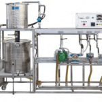
The Bench is an educational unit for the study of the technical characteristics of the three most common hydraulic turbines for the hydroelectric generation: Pelton, Francis, Kaplan. The measurements, which can be performed varying the operation conditions, can be easily compared with data resulting from the theory.
TRAINING PROGRAM
• Study of the cavitation of a centrifugal pump
• Determining the characteristic curves (head/flow rate) of a centrifugal pump
• Determining the NPSH of a centrifugal pump
• Determining the efficiency characteristics of a centrifugal pump
• Determining the characteristic torque curves at the axis of a centrifugal pump
• Determining the absorbed power characteristics of a centrifugal pump
• Study of the operation of hydraulic turbines
• Plotting of the characteristic diagram of hydraulic power as a function of the rotation speed and the opening of the distributor (Pelton, Kaplan, Francis turbine)
• Plotting of the characteristic diagram of generated power as a function of the rotation speed and the opening of the distributor (Pelton, Kaplan, Francis turbine)
• Plotting of the characteristic diagram of torque to the axis as a function of the rotation speed and opening of the distributor (Pelton, Kaplan, Francis turbine)
• Plotting of the characteristic diagram of efficiency as a function of the rotation speed and opening of the distributor (Pelton, Kaplan, Francis turbine)
TECHNICAL SPECIFICATIONS
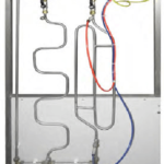
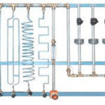
Hydraulic section:
A centrifugal pump sends the flow to the turbine under test, simulating the waterfall. The pump motor is velocity-controlled for vary the flow conditions. The turbine under test is selected by a set of valves. By measuring the water flow and pressure, it is possible to calculate the hydraulic power (Ph) supplied to the test turbine.
Mechanical section:
The turbine under test is coupled to a permanent magnets DC generator simulating a variable brake. There is only one DC generator, which is moved and coupled to the turbine under test. The electrical power is dissipated in a resistive load. By measuring the generator electrical parameters (V, I, rpm) it is possible to calculate and plot the electrical power (Pe). The Efficiency % is then calculated with Ph and Pe.
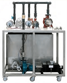
The unit includes:
• Stainless steel tank, capacity 500 l approx
• Wheeled frame
• Direct reading flow meter, 15000 l/h max
• N°2 pressure gauges 0 to 6 bar: pump outlet, turbines inlet
• Vacuum meter (pump inlet)
• Oscillating frame d.c. electric motor to operate the centrifugal pump: 4.5 kW at 3000 rpm
• Torque transducer (for DC motor)
• Speed sensor (for DC motor)
• Centrifugal pump:
– revolution speed: 2900 rpm
– power: 4 kW
– flow rate: 110 to 315 l/min
– head: 57 to 46 m H2O
• Francis turbine made of corrosion proof material with guide rotary blades and back shield made of transparent plexiglas.
• Pelton turbine made of corrosion proof material with outflow nozzle of Doble type made of stainless steel, deviation plate and glow screen made of transparent plexiglas
• Kaplan turbine made of corrosion proof material with back shield made of transparent plexiglas
• Turbine braking unit with permanent magnet DC servomotor:
– rated current 5,4 A
– rated voltage 48 V
– max power 210 W @ 3000 rpm
• Speed sensor (DC servomotor)
• Power supply: 230 Vac 50 Hz single-phase – 1,3 kVA (Other voltage and frequency on request)