Forces Suspension Bridge
Technical Specification:
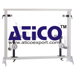
Suspension bridges are among the oldest of all bridge designs. Their main supporting element is a flexible cable. Since cables are able to absorb high tensile forces while themselves having little dead-weight, they enable wide-span suspension bridges to be constructed. This makes it possible to bridge longer distances with no supporting pillars, such as over wide gorges. The sag of suspension bridge supporting cables is parabolic in shape, as the load is attached at relatively short, constant intervals by way of vertical cables to the main supporting cables. The experimental set-up represents a suspension bridge. The bridge consists of two parallel supporting cables with a roadway suspended between them. U-shaped hangers serve as vertical cables. They are attached to the main supporting cables at regular intervals, and hold the roadway. Deflection rollers act as pylons. The roadway acts upon the supporting cables as a distributed load, and can be loaded by additional weights. It has a hinge in the middle. The hinge permits internal moments in the roadway occurring in response to uneven loading to be visualised – the roadway buckles. The tensile forces in the supporting cables are determined with the aid of weight sets. With two supports it is possible to simulate fixed roadway supports. The supports include force gauges. With the force gauges the load distribution between the supports and the supporting cable is investigated. The various elements of the experiment are clearly laid-out and housed securely in a storage system. The complete experimental set-up is arranged in the frame. The well-structured instructional material sets out the fundamentals and provides a step-by-step guide through the experiments.
Specification:
1. Investigation of a suspension bridge in various load cases
2. Suspension bridge with 2 supporting cables and roadway
3. Supporting cables with parabolic sag
4. Hangers (vertical supporting cables) in the form of U-shaped shackles in graduated lengths
5. Two-section roadway with central hinge
6. Roadway can be loaded by additional weights
7. Hinge in roadway indicates internal moments of roadway under uneven loading
8. 4 graduated weight sets to measure the cable force in both supporting cables
9. 2 supports with force gauge for the roadway
10 Storage system to house the components
11. Experimental set-up in frame.
Technical Data:
Suspension bridge
– span: approx. 1050mm
– supporting cable sag: approx. 325mm
– number of supporting cables: 2
– shackles: 12, graduated lengths
– dead-weight of roadway: 6N
Support force measuring range: -50…+50N
Weight set
– 4x 1N (hangers), 16x 1N
– 16x 5N