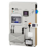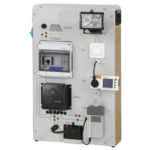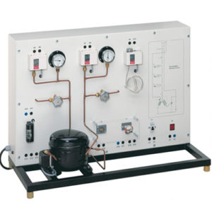
The wiring of electrical components for the start and operation of refrigerant compressors is a typical task in the field of refrigeration. Safety aspects also play an important role. With this knowledge and these skills can be acquired. All components are operated and tested with mains voltage to provide high relevance for practice. The electrical components for the start and operation of the refrigerant compressor are arranged clearly visible. The electrical connection of the individual components is made with cables via the lab jacks. The components are e.g. the capacitor and start-up relay necessary to start the motor. The circuit diagram on the front panel enables the easy allocation of the individual components.
Learning Objectives And Experiments
- Read, understand, wire and test electric circuit diagrams for refrigerant compressors
- Design and operation of electrical components of refrigerant compressors
- Start-up capacitor
- Start-up relay
- Overheat protection
- Automatic fuse
- Pressure switch
- Thermostat
- Design and testing of a safety chain
- Representation methods in electrical engineering
- Symbols
- Circuit diagrams
- Safety aspects when handling mains voltage
Specification
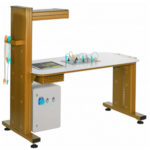
- Experimental unit from the practical series for the training of mechatronics engineers for refrigeration
- Correct electrical connection of a refrigerant compressor
- Refrigerant circuit with compressor, receiver, 2 valves and 2 manometers to investigate pressure switches on the delivery and intake sides
- Electrical components for the start and operation of the compressor mounted clearly visible
- Lab jacks and cables to connect the electrical components
- Operation of a thermostat
- Circuit diagram on the front panel for easy identification of the components
Technical Specification
- Refrigerant compressor
- power consumption: approx. 193W at 5/55°C
- refrigeration capacity: 374W at 5/55°C
- Receiver: 0,8L
- Manometer measuring ranges
- delivery side: -1…24bar
- intake side: -1…9bar
- Pressure switch control range
- delivery side: 8…32bar
- intake side: -0,9…7bar
- Thermostat: -5…35°C
- Electrical components for the compressor
- start-up capacitor
- start-up relay
- overheat protection (bimetallic)
- automatic fuse
- Refrigerant
- R513A
- GWP: 631
- filling volume: 300g
- CO2-equivalent: 0,2t
- 230V, 50Hz, 1 phase
- 230V, 60Hz, 1 phase; 120V, 60Hz, 1 phase