Deformation of Straight Beam
Technical Description:
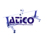
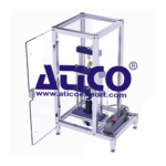
Beams are key structural elements in mechanical engineering and in construction. A beam is a bar-shaped component in which the dimensions of the cross-section are much smaller than the length and which is subjected to load along and perpendicular to its longitudinal axis. The load perpendicular to the longitudinal axis causes a deformation of the beam – that is, bending. Based on its size, the beam is viewed as a one-dimensional model. The science of the strength of materials deals with stress and strain resulting from the application of load to a component. Many fundamental principles of the strength of materials can be illustrated well by a straight beam. The beam under investigation can be supported in different ways. This produces statically determinate and indeterminate systems which are placed under load by up to four sets of weights. The load application points are movable. Three dial gauges record the resulting deformation. Three articulated supports with integral force gauges indicate the support reactions directly. The articulated supports are height-adjustable, so as to compensate for the influence of the dead- weight of the beam under investigation. A fourth bearing clamps the beam in place. Five beams of different thicknesses and made of different materials demonstrate the influence of the geometry and of the modulus of elasticity on the deformation of the beam under load. The various elements of the experiment are clearly laid-out and housed securely in a storage system. The complete experiment setup is arranged in the frame. The well-structured instructional material sets out the fundamentals and provides a step-by-step guide through the experiments.
Specification:
1. Elastic lines of statically determinate and indeterminate beams under various clamping conditions
2. 3 steel beams with different cross-sections
3. 1 brass and 1 aluminium beam
4. 3 articulated, height-adjustable supports with force gauge
5. 1 support with clamp fixing
6. Force gauges can be zeroed
7. 3 dial gauges to record deformations
8. 4 sets of weights with adjustable hooks
9. Anodised aluminium section frame housing the experiment
10. Storage system to house the components
Technical Data:
Beam
– length: 1000mm
– cross-sections
3x20mm (steel)
4x20mm (steel)
6x20mm (steel, brass, aluminium)
Frame opening: 1320x480mm
Measuring ranges
– force: -50..+50N, graduations: 1N
– travel: 0…20mm, graduations: 0,01mm
Weights
– 4x 2,5N (hanger)
– 4x 2,5N
– 16x 5N