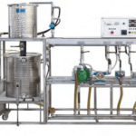
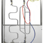
The bench is a computerized table-top unit for the study of the technical characteristics of the Kaplan hydraulic
turbine. The unit is real and totally operational: in fact, it allows to modify the operation conditions and to compare the practical data with the theory. A real-time data acquisition and analysis system is included that also features an automatic data acquisition for further in-depth study of the topic.
TRAINING PROGRAM
The unit allows to vary the rotational speed to determine:
• Hydraulic power curve vs. rpm and shutter opening
• Electrical generator power vs. rpm and shutter opening
• Efficiency as a function of the rpm and shutter opening
• Axial torque characteristic
TECHNICAL SPECIFICATIONS
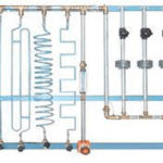
Hydraulic section:
A centrifugal pump elevates the flow to turbine, simulating the waterfall. The pump motor speed is frequency-controlled by an inverter. By measuring the water flow and pressure, it is possible to calculate the hydraulic power (Ph) supplied to the turbine.
Mechanical section:
The turbine is coupled to a permanent magnets DC generator simulating a variable brake. The electrical power is dissipated in a resistive load. By measuring the generator electrical parameters (V, I, rpm) it is possible to calculate and plot the electrical power (Pe). The efficiency (%) is then calculated with Ph and Pe.
Electro-Hydraulic section:
• Centrifugal pump: 0,75 kW; 2900 giri/min; Q = 110 ÷ 250 l/min; ΔH = 18 ÷ 14 m
• Stainless steel tank, approx. 60 litres
• Flow transducer 25-250 l/min – 4…20 mA output
• Pressure transducer 0-4 bar – 4…20 mA output
• Pressure gauge with dial 0 ÷ 4 bar
• Guidable blades distributor
• Stainless steel Kaplan turbine
• Permanent magnets DC generator, performing as variable electrical brake. Nominal parameters: 48 V, 210 W at 3000 rpm
• Digital rpm transducer
Control section with signal conditioning and A/D conversion:
• Centrifugal pump supervision: programmable inverter for rpm control
• Electronic board with display to check: pump flow rate and pressure; DC generator electrical parameters: V, I, rpm; Ph, Pe and efficiency (the DC generator losses are provided by the manufacturer)
• Signals conditioning unit with 12 bit A/D conversion. The board is connected to a PC via USB port.
• Data acquisition and analysis software running under Windows: it automatically acquires data in real-time from the system transducers that are also used for fault simulation. The software can also display, save and print the unit performance diagrams.
• Resistive load for the DC generator
• Power supply: 230 Vac 50 Hz single-phase – 1,3 kVA (Other voltage and frequency on request