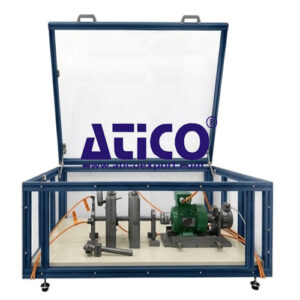
Base Unit : Includes Software, Sensors, and Control for the base unit – Displacement Sensors
Base Unit. Main metallic elements made of stainless steel and includes as below :-
Asynchronous Motor with frequency variator, with sliding support and two micrometers; Drive Power: 0.37 kW, Nominal Speed : 2800 RPM. Adjustable power and speed.
Shafts : 2 Nos.; Short Shaft : dia. – 20 mm, Length : 300 mm
Long Shaft : dia. – 20 mm, Length : 500 mm
Flexible Motor-shaft Couplings: 3 Nos., in order to compensate for possible misalignments.
Bearing Sawhorses: 2 Nos., Ball bearings 6204-SKF.
Flywheels: 2 Nos., unbalanced with removable counterweights (screws), thus allowing the balancing in one or two plane; dia. : 150 mm, Weight : 1700 gm each.
Tachometer: Provided for recording the speed.
Toolkit and Screws: Provided for assembly of all components.
Storage Case : Provided
Electronic Console : Made of Metal Box, includes Main Switch, Speed Sensor Connector, Motor
Connector, Motor Start Switch, Motor Stop Switch, Motor Rotation Switch, Motor Controller by Potentiometer, Digital Display for Motor Speed, Digital Display for Motor Power, Software, Sensors, and Control Two acceleration sensors for recording oscillation travel,
Oscillation Speed and Acceleration : Frequency Range : 1 – 10 KHz, Sensitivity : 100 mV/g.
Resonance Frequency of about 32 kHz.
Optical Tachometer Sensor : Range : 100 – 60000 RPM
Optical Range : up to 2 mtr. Class 2 laser of 675 nm. USB connection.
Inductive Displacement Sensors : 2 Nos., Range: 1 – 10 mm.
Configuration : The complete unit includes :-
• Advanced Real-Time SCADA, Open Control + Multicontrol + Real-Time Control, Specialized Control Software based on LabVIEW.
• National Instruments Data Acquisition board (250 KS/s, kilo samples per second).
• Calibration Exercises, which are included, teach the user how to calibrate a sensor and the importance of checking the accuracy of the sensors before taking measurements.
• Projector and/or electronic whiteboard compatibility allows the unit to be explained and demonstrated to an entire class at one time. Capable of doing applied research, real industrial simulation, training courses, etc. Remote operation and control by the user and remote control for technical support, are always included.
• Totally safe, utilizing 4 safety systems (Mechanical, Electrical, Electronic & Software). Designed and manufactured under several quality standards. Software to create, edit and carry out practical exercises, tests, exams, calculations, etc. Apart from monitoring user’s knowledge and progress reached. This unit has been designed for future expansion and integration. A common expansion is the Scada-Net (ESN) System which enables multiple students to simultaneously operate many units in a network.
Base Unit Mobile Structure : Mobile table for the Base Unit, Dimensions : 1100 x 770 x 820 mm.
Construction : Mobile Structure, Made of Anodized Aluminum Frames. Aluminum frame assembly without mechanization. Transparent protective cover with safety switch. Diagram in the front panel with distribution of the elements similar to the real one. Wheeled Laboratory Bench. Anodized aluminum frames. Aluminum frame assembly without mechanization. Four steering wheels with brakes on two of them. Two shelves for the accessories.
Additional Elements:-
Break and Load Unit : The set consists mainly of following :- Magnetic Particle Brake (adjustment and
measurement of the braking torque) : Speed Range : 200 – 2000 RPM, Braking Torque : 10 Nm. Adjustment and measurement of the braking torque.
Integrated Belt Drive for Second : Gear ratio between brake shafts: i = 3. Speed range: 600 – 6000 rpm.
Speed Range & Moment Range Braking torque: 3.3 Nm. Axial fan for heat discharge.
Electric Protection : against superheating Electronic console: Main switch. Brake switch. Brake controller.
Digital display of brake excitation current.
Set of Elastic Shaft : This set consists primarily of Two elastics shafts made of high-grade steel:
Diameter : 10 mm. Length: 550 mm. Nominal length between bearings: 450 mm. Three bearings with holes for sensor housing. Two bearing supports with oscillating ball bearings. Vibration amplitude limitation bearing, diameter: 20 mm. Storage case.
Set of Rotating Shaft with Crank : The set consists mainly of following :–
• Taker-in plate.
• Flange with short shaft (additional recommended element Set of Belt Drive, Diameter: 90 mm.
• Flange with long shaft (for flywheel). Diameter: 90 mm.
• Six screws: Hexagon head screw for flange M8 x 20.
Clamping Kit : The set consists mainly of following:-
• Two Shafts : Diameter: 20 mm.
Short Shaft for “Projecting Shaft End” Simulation :Length : 85 mm max. allowable bending moment: 15.9 Nm
• Long Shaft for “Elastic Rotor” Simulation :Length : 200 mm max. allowable bending moment: 3.9 Nm
• Centering mandrel for shaft alignment during the test assembly.
Set of Roller Bearings with Faults : The set consists mainly of following:-
• Six oscillating ball bearings : Inner diameter: 20 mm. Outer diameter: 47 mm. Width: 14 mm. Number of balls: 12.
Bearings : • Bearing with damaged outer ring.
• Bearing with damaged inner ring.
• Bearing with damaged rolling element.
• Bearing with combined damage.
• Widely used bearing.
• New and non-faulty bearing Roller bearing bracket.
• Retaining rings.
• Tool for retaining rings.
Set of Couplings : The set consists mainly of following :-
• Curved tooth coupling.
• Non-faulty flange coupling.
• Flange coupling with eccentricity fault : Eccentricity Fault (non-centering): 0.2 mm.
• Flange coupling with oscillation fault: Oscillation fault: 0.4 ± 0.1 mm.
• Bolt coupling with variable pitch fault : Non-eccentric bolt.
• Eccentric bolt: Bolt eccentricity: 1 mm. Max. pitch error: 180° ± 1.909°.
• Four stars for claw coupling : 98 Shore A (red). 92 Shore A (yellow). 64 Shore D (green). 80 Shore A (blue).
• Roller bearing bracket with elastic support.
Set of Belt Drive : The set consists mainly of following :-
• Rubber V-belt: SPX profile, approx. 10 mm wide. Belt length: 915 mm.
• Damaged rubber V-belt: SPX profile, approx. 10 mm wide. Belt length: 915 mm.
• Small drive pulley: Diameter: 63 mm.
• Small pulley with eccentricity fault for the V-belt: Diameter: 63 mm.
• Large pulley: Diameter: 125 mm. Distance between shafts: 300 mm.
Clamping Kit : The set consists mainly of following:-
• Belt pre-tension meter: 0 – 150 N. Belt tensioning device.
• Individually adjustable tensor rollers. V-belt tension adjustment.
Set to Study Damage in Gears : The set consists mainly of following:-
• Transparent box cover to observe the gear in operation.
• Holes for vibration sensors.
• Sets of straight-toothed gears, with fault: Sprocket wheel: 75 teeth each, m= 2. Pinion: 25 teeth each, m= 2.
• Sets of straight-toothed gears, without fault: Sprocket wheel: 75 teeth each, m= 2. Pinion: 25 teeth each, m= 2.
vSets of helical-toothed gears, with fault: Sprocket wheel: 75 teeth each, m= 2. Pinion: 25 teeth each, m= 2.
• Sets of helical-toothed gears, without fault: Sprocket wheel: 75 teeth each, m= 2. Pinion: 25 teeth each, m= 2.
• Gear fixing shafts. Variable wheelbase.
• Motor oil SAE 10 W – 40, 1 l for lubricating the gears.
• Storage case.
Set of Crank Mechanism : The set consists mainly of following:-
• Crank and connecting rod mechanism with adjustable stroke: Stroke: 50 – 75 – 100 mm.
• Two balance weight masses: Total 490 g, designed to operate with a 50 mm stroke.
• Bearing set adjustment: Bearing clearance: 0 – 1 mm
• Two pressure springs: Length without tension: 170 mm. Spring ratio: R = 0.55 N/mm
Set to Study Cavitation in Pumps : The set consists mainly of following:-
• Centrifugal Pump : Max. flow rate: 17 l/min (3300 min-1). Max. lift height: 12 m (3300 min-1). Three-vane impeller. Minimum speed for cavitation: 2240 min-1 approx. (choked suction side).
• Two manometers: Pressure side: 0 – 4 bar. Suction side: -1 – 1.5 bar.
• Casing cap. Knurled screw to open the casing cap.
• Suction side tube.
• Two ball valves.
• Set of flexible tubes.
• Tank: Material: HDPE. Capacity: 20 Ltrs.
Blower Vibration Set : The set consists mainly of following :-
• Steel plate impeller with three movable vanes: Diameter: 204 mm. Max. speed: 3000 min-1.
• Steel plate impeller with five movable vanes: Diameter: 204 mm. Max. speed: 3000 min-1.
• Steel plate impeller with seven movable vanes : Diameter: 204 mm. Max. speed: 3000 min-1.
• Flywheel plate to simulate axial forces.
• Protective cover. Roller
• Bearing bracket.
• Aluminum protective plate, diameter: 220 mm.
• Permanent magnet.
Set of Electromechanical Vibrations : The set consists mainly of following:-
• Asynchronous Motor with Variable Speed : Drive power: 0.37 kW. Nominal speed: 2800 rpm. Adjustable power and speed. Variable air gap due to stator displacement. Winding disconnect switch. Current clamp. Adjustable magnet-vane distance.
• Brake and Load unit Control Interface Box : The Control Interface Box is part of the SCADA system. Control interface box with process diagram in the front panel. The unit control elements are permanently computer controlled. Simultaneous visualization in the computer of all parameters involved in the process.
Sensor Calibration : It involved in the process. Real time curves representation about system responses.
All the actuators’ values can be changed at any time from the keyboard allowing the analysis about curves and responses of the whole process. Shield and filtered signals to avoid external interferences. Real time computer control with flexibility of modifications from the computer keyboard of the parameters, at any moment during the process. Real time computer control for parameters involved in the process simultaneously. Open control allowing modifications, at any moment and in real time, of parameters involved in the process simultaneously. Three safety levels, one mechanical in the unit, another electronic in the control interface and the third one in the control software. DAB.
Data Acquisition Board : The Data Acquisition board is part of the SCADA system. PCI Express
Data acquisition board (National Instruments) is placed in a computer slot.
Analog Input : Channels= 16 single-ended or 8 differential. Resolution=16 bits, 1 in 65536. Sampling rate up to: 250 KS/s (kilo samples per second).
Analog Output: Channels=2. Resolution=16 bits, 1 in 65536.
Digital Input/Output: Channels=24 inputs/outputs.
The Data Acquisition board model may change at any moment, providing the same or better features than those required for the unit. Computer Control + Data Acquisition + Data Management Software: The three software are part of the SCADA system. Compatible with the industry standards. Flexible, open and multi-control software, developed with actual windows graphic systems, acting simultaneously on all process parameters. Management, processing, comparison and storage of data. Sampling velocity up to 250 KS/s (kilo samples per second). Calibration system for the sensors involved in the process. It allows the registration of the alarms state and the graphic representation in real time.
Open software, allowing the teacher to modify texts, instructions. Teacher’s and student’s passwords to facilitate the teacher’s control on the student and allowing the access to different work levels. This unit allows the 30 students of the classroom to visualize simultaneously all the results and the manipulation of the unit, during the process, by using a projector or an electronic whiteboard. Cables and Accessories, for normal operation.
Manuals : Assembly and Installation, Interface, and Control software, Starting-up, Safety,
Maintenance, Calibration & Practices manuals.
Additional Items : As listed below :-
a) Industrial configuration PLC. Industrial Control using PLC (it includes PLC-PI Module plus PLC-SOF Control Software):
• PLC-PI. PLC Module : Metallic box. Circuit diagram in the module front panel. Digital inputs (X) and Digital outputs (Y) block: 16 Digital inputs. 14 Digital outputs. Analog inputs block: 16 Analog inputs. Analog outputs block: 4 Analog outputs. Touch screen. Siemens PLC: High-speed scan of 0.32 µsec. Program capacity of 32 Ksteps. High-speed counter. Multi-point PID control. Digital inputs/outputs and analog inputs/outputs Panasonic modules.
• PLC Control Software : For this unit, always included with PLC supply. Practices to be done with:
1. Control of the particular unit process through the control interface box without the computer.
2. Visualization of all the sensors values used in the particular unit process.
3. Calibration of all sensors included in the particular unit process.
4. Hand on of all the actuators involved in the particular unit process.
5. Realization of different experiments, in automatic way, without having in front the particular unit. (These experiments can be decided previously).
6. Simulation of outside actions, in the cases do not exist hardware elements. (Example: test of complementary tanks, complementary industrial environment to the process to be studied, etc.).
7. PLC hardware general use.
8. PLC process application for the particular unit.
9. PLC structure.
10. PLC inputs and outputs configuration.
11. PLC configuration possibilities.
12. PLC program languages.
13. PLC different programming standard languages (ladder diagram (LD), structured text (ST), instructions list (IL), sequential function chart (SFC), function block diagram (FBD)).
14. New configuration and development of new process.
15. Hand on an established process.
16. To visualize and see the results and to make comparisons with the particular unit process.
17.-Possibility of creating new process in relation with the particular unit.
18. PLC Programming Exercises.
19. Own PLC applications in accordance with teacher and student requirements.
b) Technical and Vocational Education configuration Interactive Computer Aided Instruction Software.
This complete software package consists of an Instructor Software (Classroom Manager) totally integrated with the Student Software. Both are interconnected so that the teacher knows at any moment what is the theoretical and practical knowledge of the students. – Classroom Manager (Instructor Software). Classroom Manager is an application that allows the Instructor to register students, manage and assign tasks for workgroups, create own content to carry out Practical Exercises, choose one of the evaluation methods to check the Student knowledge and monitor the progression related to the planned tasks for individual students, workgroups, units, etc. so the teacher can know in real time the level of understanding of any student in the classroom.
Innovative Features :–
User Data Base Management.
Administration and assignment of Workgroup, Task and Training sessions.
Creation and Integration of Practical Exercises and Multimedia Resources.
Custom Design of Evaluation Methods.
Creation and assignment of Formulas & Equations.
Equation System Solver Engine.
Updatable Contents.
Report generation, User Progression Monitoring and Statistics.
Student Software : Student Software is an application addressed to the students that helps them to understand theoretical concepts by means of practical exercises and to prove their knowledge and progression by performing tests and calculations in addition to Multimedia Resources. Default planned tasks and an Open workgroup are provided to allow the students start working from the first session. Reports and statistics are available to know their progression at any time, as well as explanations for every exercise to reinforce the theoretically acquired technical knowledge.
Innovative Features:-
Student Log-In & Self-Registration.
Existing Tasks checking & Monitoring.
Default contents & scheduled tasks available to be used from the first session.
Practical Exercises
Evaluation Methods to prove your knowledge and progression.
Test self-correction.
Calculations computing and plotting.
Equation System Solver Engine.
User Monitoring Learning & Printable Reports.
Multimedia-Supported auxiliary resources.
Faults Simulation System : Faults Simulation System (FSS) is a Software package that simulates several faults
in any the Computer Controlled Unit. The “FAULTS” mode consists in causing several faults in the unit normal operation. The student must find them and solve them. There are several kinds of faults that can be grouped in following sections :-
Faults affecting the sensors measurement :–
• An incorrect calibration is applied to them.
• Non-linearity.
Faults affecting the actuators :–
• Actuators channels interchange at any time during the program execution.
• Response reduction of an actuator.
• Faults in the controls execution :–
• Inversion of the performance in ON/OFF controls.
• Reduction or increase of the calculated total response.
• The action of some controls is annulled.
On/off Faults :-
• Several on/off faults can be included.
c) Multi-post Expansions options MINI ESN.
Mini Scada-Net System for being used with the Teaching Units : It allows up to 30 students to work with a Teaching Unit in any laboratory, simultaneously. The system consists of the adaptation of any Computer Controlled Unit with SCADA integrated in a local network. This system allows to view / control the unit remotely, from any computer integrated in the local net (in the classroom), through the main computer connected to the unit.
Main Characteristics:-
– It allows up to 30 students to work simultaneously with the Computer Controlled Unit with SCADA, connected in a local net.
– Open Control + Multi-control + Real Time Control + Multi Student Post.
– Instructor controls and explains to all students at the same time.
– Any user/student can work doing “Real Time” control/multi-control and visualisation.
– Instructor can see in the computer what any user/student is doing in the unit.
– Continuous communication between the instructor and all the users/students connected.
Main Advantages:-
It allows an easier and quicker understanding.
This system allows you can save time and cost.
Future expansions with more Units.
The system basically will consist of following :-
This system is used with a Computer Controlled Unit.
Instructor’s computer.
Students’ computers.
Local Network.
Unit-Control Interface adaptation.
Unit Software adaptation.
Webcam.
Mini-ESN Software to control the whole system.
Cables and accessories required for normal operation.
Computer Controlled Machine Diagnosis Unit, with SCADA 2