The Efficient Control Of The Capacity And Temperature In Refrigeration Systems Is An Important Topic In Refrigeration Technology. With Different Methods Of Capacity Control Can Be Investigated.
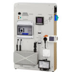
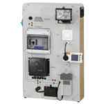
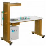
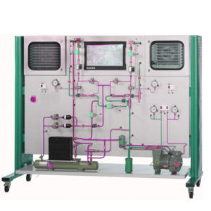
The Components Of A Refrigeration Circuit With Refrigeration And Freezing Chambers Are Arranged Clearly In The Trainer. Solenoid Valves Enable The Separate Or Parallel Operation Of The Evaporators In The Two Chambers. The Circuit Is Equipped With A Capacity Controller, A Start-Up Controller And A Combined Pressures Switch For The Delivery And Intake Sides Of The Compressor. One Heat Exchanger Each In The Inlet Of The Two Evaporators Enables The Supercooling Of The Refrigerant To Be Investigated For The Efficiency Of The Process. The Refrigeration Capacity Of The Two Individual Chambers Is Controlled By A Thermostat. The Refrigeration Chamber Also Features An Evaporation Pressure Controller.
Learning Objectives And Experiments
- Familiarisation With The Key Devices For Changing The Refrigeration Capacity
- Thermostat
- Capacity Controller
- Start-Up Controller
- Evaporation Pressure Controller
- Condensation Pressure Controller
- Fault Finding In Refrigeration System Components
- Effect Of Refrigerant Supercooling
- Familiarisation With Defrosting Methods
- Electric Defrost Heater
- Hot Gas Defrosting
- Representation Of The Thermodynamic Cycle In The Log P-H Diagram
Specification
- Investigation Of A Refrigeration System With Refrigeration And Freezing Chambers
- Refrigeration Circuit With Compressor, Condenser, Capacity Controller, Start-Up Controller, Combined Pressure Switch And 2 Evaporators In Insulated Chambers
- Each Chamber With Solenoid Valve, Thermostat, Thermostatic Expansion Valve, Fan And Heat Exchanger For Refrigerant Supercooling
- Refrigeration Chamber With Evaporation Pressure Controller
- Freezing Chamber With Electric Defrost Heater And Hot Gas Defrosting
- Separate Or Parallel Operation Of The Chambers Via Solenoid Valves
- Simulation Of 12 Faults
- Touch Panel PC For Fault Activation, Data Acquisition, Evaluation And Representation In The Log P-H Diagram
Technical Specification
- Compressor
- Refrigeration Capacity: 1640W At -10/50°C
- Power Consumption: 980W At -10/50°C
- Condenser With Fan
- Volumetric Air Flow Rate: 570m3/H
- Evaporator Transfer Areas
- Refrigeration Chamber: 1,12m2
- Freezing Chamber: 1,88m2
- Electric Defrost Heater: Approx. 125W
- Capacity Controller: 0,2…6bar
- Start-Up Controller: 0,2…6bar
- Thermostat: 2x -25…15°C
- Evaporation Pressure Controller: 0…5,5bar
- Refrigerant
- R449A
- GWP: 1397
- Filling Volume: 3,21kg
- CO2-Equivalent: 4,5t
- Measuring Ranges
- Temperature: 6x -50…50°C; 5x 0…100°C
- Pressure: 3x -1…15bar; 2x -1…24bar
- Flow Rate: 2x 2…29L/H
- Power Consumption: 0…5kw (Compressor)
- 400V, 50Hz, 3 Phases
- 230V, 60Hz, 3 Phases; 400V, 60Hz, 3 Phases