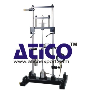
Buckling Behaviour of Bars
Technical Description:
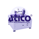
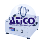
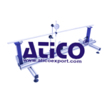
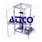
In technical mechanics, loss of stability is known as buckling. Under the effects of compressive forces, and under increasing load, the axis of the bar deflects laterally until it suddenly and violently fails (collapses), even before the fracture point is reached. The stresses in the bar often remain within the elastic range during this process. Investigates the buckling behaviour of bars under various influences. All relevant buckling problems are demonstrated by way of experimentation. For the purpose, one end of a bar is fixed or pinned, depending on the buckling case. A height-adjustable load-carrying cross-arm and a hand-operated spindle are used to apply compressive force to the bar. An axial bearing between the spindle and the bar support prevents torsional loading of the test bar. A hydraulic load cell measures the applied force and indicates it on a pressure gauge. The lateral deflection of the bar is indicated on a dial gauge. Experiments demonstrate various influences, such as bar lengths, materials and methods of support. A transverse load application device can be used to generate additional shear forces on the test bar. The experimental unit can be operated vertically or horizontally. The load gauge can be rotated 90° to adjust to the chosen option. The various elements of the experiment are clearly laid-out and housed securely in a storage system.
Specification:
1. Investigation and testing of all relevant buckling cases
2. Verification of the Euler Theory of buckling
3. Experiments in horizontal or vertical orientation
4. Test bars in various lengths and materials
5. Test bar ends pinned or fixed
6. Spindle to apply forces
7. Transverse load application device generates shear forces
8. Force measurement using a hydraulic load cell
9. Measurement of lateral deflection by dial gauge
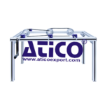
10. Storage system to house the components
Technical Data:
Test bars
– quantity: 11
– bar length: 350…700mm (max.)
– materials: aluminium, copper, brass, steel, GRP
– cross-sections: 10x4mm, 25x6mm, 25x10mm
Load application spindle
– force: max. 2000N
– stroke: max. 10mm
Lateral deflection: max. 20mm
Specimen holder bore: d=20mm
Measuring ranges
– force: 0…2500N, graduations: 50N
– deflection: 0…20mm, graduations: 0,01mm
Set of weights for transverse load: max. 20N
– 3x 5N, 1x 5N (hanger)