Description:
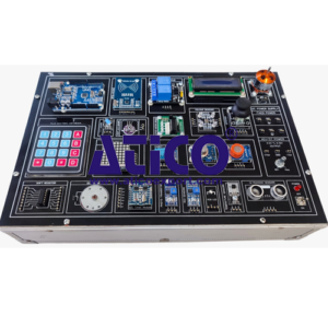
System Overview : The training system should consist of the following 7 modules: (Set of Seven Module with Function Generator & DC Power Supply Module)
- 8 Bits LED Circuit: Output data length 8 bits and LED display as data display mode
- 6 Bits PWM LED Circuit: Output data length 6 bits and LED display as data display mode
- 4 Bits Push Button Switch Circuit: Output data length 4 bits and LED display
Arduino Microcontroller I: as data display mode
- 4 Bits DIP Switch Circuit: Output data length 4 bits and LED display as data display mode
- Self-drive Buzzer
- External Drive Buzzer
- Relay Switch Circuit
- 7-segment Display Circuit
- 16 x 8 LED Matrix Circuit: Serial data input mode and 16 x 8 LED matrix display as display mode
- 16 x 2 LCD Displayer: Serial data input mode and 16 x 2 LCD display as display mode
Arduino Microcontroller II :
- 4 x 4 Matrix Keypad: 4 x 4 matrix keypad input mode and 16 x 2 LCD display as display mode
- ADC Circuit: Analog voltage input mode and 16 x 2 LCD display as display mode
- DAC Circuit: PWM input mode and analog voltage output mode
- DS1307 Clock Module and Full Color RGB LEDs
Applications of Arduino Microcontroller (I) :
- Photo Sensor Circuit: Operating wavelength of 500nm ~ 580nm
- Tilt Switch Circuit: Conduction angle of 55° ~ 125°
- Vibration Switch Circuit
- Ultrasonic Sensor and Buzzer
- Temperature and Humidity Sensor Board: 0 ~ 50°C temperature and 20% ~ 90% RH Humidity measurement range
Applications of Arduino Microcontroller (II)
- Magnetic Sensor Circuit: Detects a magnetic field (Sensor mode) and uses a 16 x 2 LCD Display (Display mode) to show data.
- Volume Sensor Circuit: Processes audio (Sensor mode) and utilizes an LED Display (Display mode).
- Alcohol Sensor Circuit: Features a sensitivity of 100ppm.
- Gas Sensor Circuit: Provides a sensitivity of 5000ppm for methane.
- RFID Sensor Circuit: Uses an RFID Tag for input and a 16 x 2 LCD Display for the output display.
- Brushless DC Motor: Push button switch (Input mode) and Brushless DC motor (Output mode) • Forward and Reverse DC Motor: Push button switch (Input mode) and DC motor of forward or reverse (Output mode)
Applications of Arduino Microcontroller (III) :
- Bipolar Stepper Motor: Push button switch (Input mode) and Bipolar stepper motor (Output mode)
- Unipolar Stepper Motor: Push button switch (Input mode) and Unipolar stepper motor (Output mode)
- Servo Motor: Push button switch (Input mode) and Servo motor of angle (Output mode)
Integrated Applications of Arduino Microcontroller (I)
- 74HC595 shift register circuit
- Infrared human body sensor circuit
- XY joystick circuit and Servo motor
Integrated Applications of Arduino Microcontroller (II)
- Infrared gesture detection circuit
- Infrared remote control circuit
- Countdown timer circuit
Function Generator and DC Power Supply Module. :
- Waveforms: Sine, Triangle, Square, and TTL
- Amplitude: Greater than 10 Vpp (Volts peak-to-peak).
- Impedance: 50Ω ± 10%.
- Duty Control: 30% – 60%.
- Display: 6-Digit LED
- Frequency Range:
- 10 Hz ~ 100 kHz (distributed across 4 ranges).
- 100 Hz ~1 MHz (distributed across 4 ranges).
- Frequency Control: Features separate Coarse and Fine Tuning knobs.
- Constant Voltage Output: ±5V, ±12V.
- Variable Voltage Output: OV ” ±15V.
- Power Source: 220 ~ 230V AC, 50Hz, 1 Phase.
- Accessories: Includes standard accessories and a printed operation manual.